Power Management / PoE / Embedded Power Distribution
Mini PoE Priority 12V Power Distribution Board
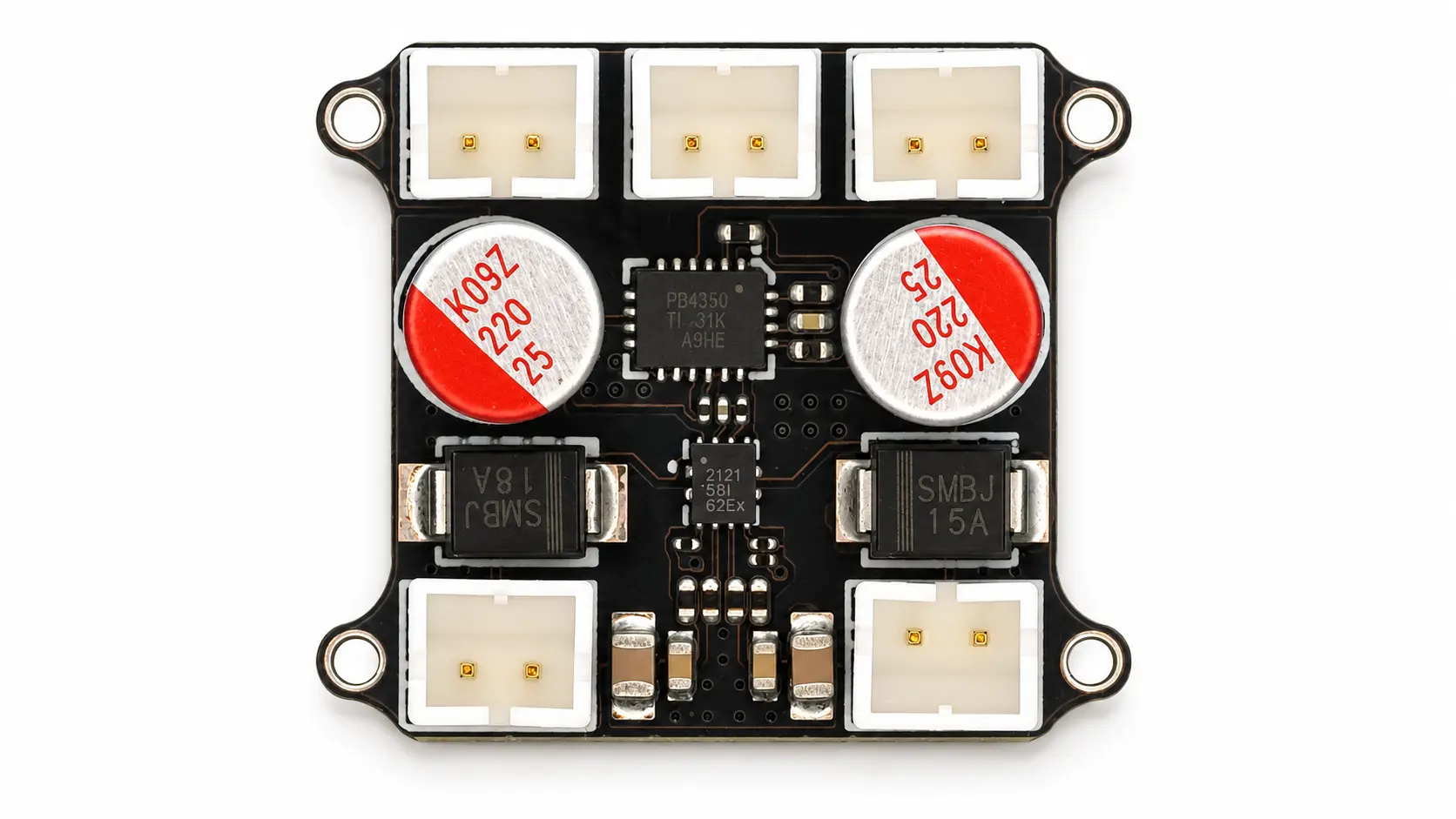
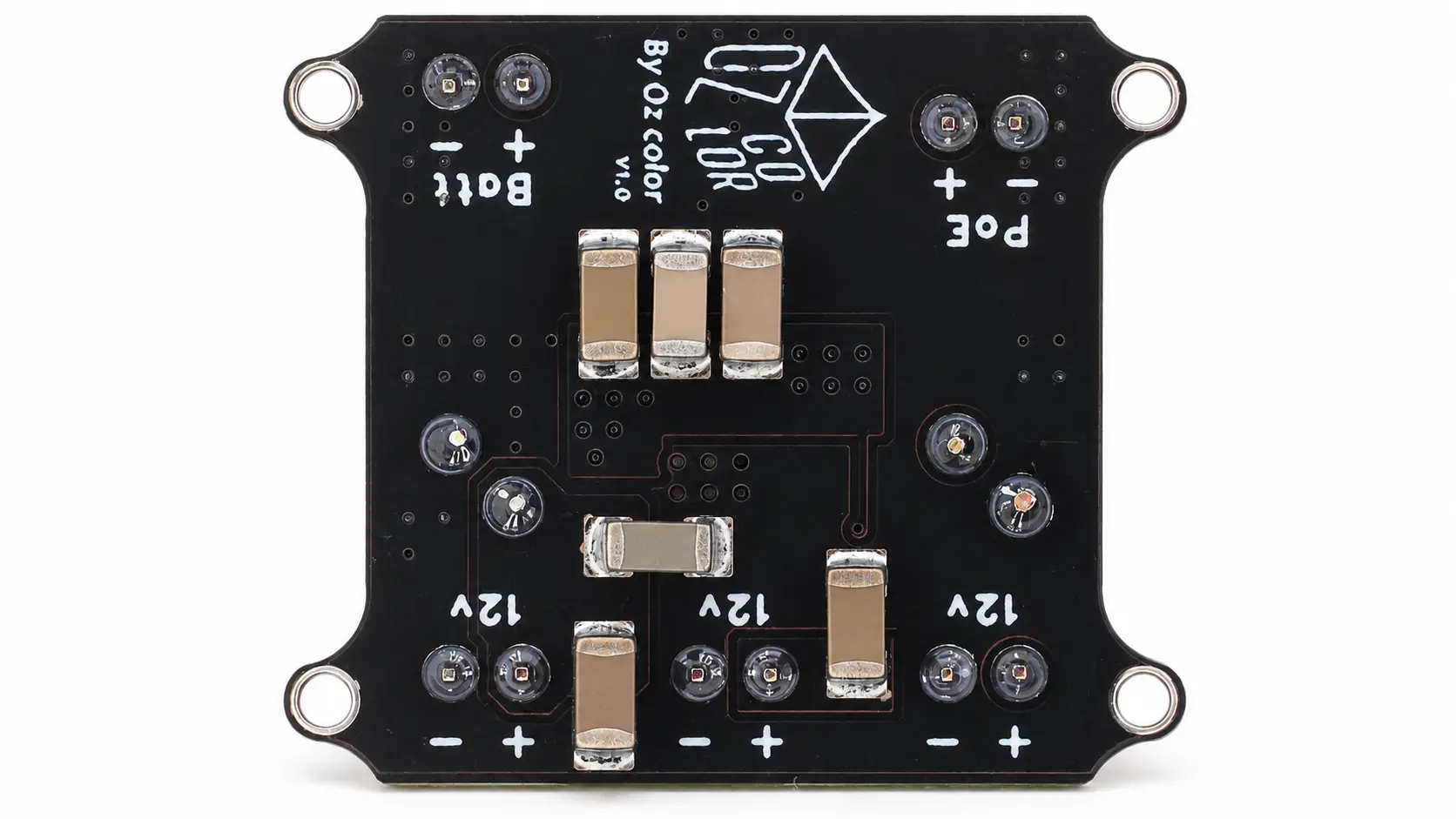
A compact 30×30 mm 2-layer power distribution board designed to accept either a 12–15V DC input or PoE-based input, automatically prioritize PoE when both sources are connected, and provide three protected 12V outputs through JST connectors.
PROJECT GALLERY
Project Gallery
OVERVIEW
Overview
This project is a compact power input and distribution PCB designed for embedded electronics, IoT devices, camera systems, control modules, automation hardware, and small electronic systems that require a reliable 12V supply from more than one source.
The board supports two power input paths: a direct 12–15V DC input and a PoE-based input. When both power sources are connected at the same time, the onboard power-path circuit automatically gives priority to the PoE input. This makes the board suitable for systems where Ethernet/PoE should be the preferred operating source, while the auxiliary 12–15V input can act as a secondary or backup supply.
The board distributes the selected 12V rail to three JST output connectors. Each output path is protected and current-limited, with a default current limit of 2A per output. The output current limit can also be adjusted based on the final application requirement.
KEY FEATURES
Key Features
TECHNICAL SPECIFICATIONS
| Board Function | PoE-priority 12V power distribution board |
|---|---|
| Input Sources | 12–15V DC input and PoE input |
| Priority Logic | PoE is automatically prioritized when both inputs are connected |
| Active Rail | Protected 12V distribution rail |
| Target Use | IoT devices, camera systems, embedded controllers, and compact automation hardware |
| Output Channels | 3× protected 12V outputs |
|---|---|
| Connector Type | JST output connectors |
| Current Limit | 2A default per output |
| Current Adjustment | Output current limit can be adjusted based on application requirements |
| Hot-Swap Support | Supported for safer load connection and disconnection |
| Input Protection | Over-voltage, under-voltage, ESD, over-current, and over-temperature protection |
|---|---|
| Output Protection | Over-voltage, under-voltage, ESD, over-current, and over-temperature protection |
| Short-Circuit Behavior | Current-limited output protection behavior |
| Power-Path Safety | Automatic source selection prevents unsafe dual-input behavior |
| Reliability Focus | Designed for real-world cable connection, load changes, and embedded system use |
| PCB Size | 30 × 30 mm |
|---|---|
| Layer Count | 2-layer PCB |
| Copper Weight | 1 oz copper |
| Board Type | Compact embedded power distribution PCB |
| Layout Focus | Small footprint, protected power routing, JST output access, and production-friendly assembly |
TEST RESULTS
Test Results
| Test Area | Validation Method | Status | Result / Notes |
|---|---|---|---|
| 12–15V DC input validation | Power the board through the auxiliary 12–15V DC input and verify stable 12V output distribution. | Verified | The board operated correctly from the direct 12–15V input path during testing. |
| PoE input validation | Power the board through the PoE input path and verify that the selected power rail is distributed to the 12V outputs. | Verified | The PoE input path was tested and confirmed functional. |
| Input priority validation | Connect both the 12–15V DC input and PoE input at the same time, then verify which source powers the board. | Verified | When both inputs were connected, the board correctly prioritized the PoE input. |
| 12V output rail validation | Verify the regulated/protected 12V output rail across the available JST output connectors. | Verified | The 12V output rail was verified across the board output section. |
| JST output connector check | Check all three JST output connectors for correct power delivery and output availability. | Verified | All three 12V JST output connectors were tested and confirmed working. |
| Current limit behavior check | Review and test output current-limited behavior according to the default 2A output configuration. | Verified | Each output is designed with a default 2A current limit, which can be adjusted based on the final product requirement. |
| Protection behavior validation | Review protection behavior for abnormal input/output conditions, including over-current, voltage-related events, and thermal protection response. | Verified | Input and output protection behavior was validated during project testing. |
| Hot-swap support check | Connect and disconnect output loads during operation to verify safer load connection behavior. | Verified | The board supports hot-swap load connection for practical embedded system use. |
| Client functional confirmation | Final board behavior reviewed and confirmed after client-side testing. | Verified | The client confirmed that the board worked as expected after testing. |
DELIVERABLES
Deliverables
Project Inquiry
Need a Compact Protected Power Distribution Board?
Send your input voltage, output requirements, connector preference, and protection needs to get a reliable power board designed for your hardware.