STM32 / RF Receiver / SBUS / PPM / Embedded Control
Mini SBUS / PPM 2.4GHz Receiver Board
A compact 2.4GHz mini receiver board designed with STM32F103C8T6 and nRF24L01+ PA+LNA, supporting SBUS and PPM output for RC control applications with 5V input, bind indication, power status LED, long-range RF support, and low-power receiver operation.
PROJECT GALLERY
Project Gallery
OVERVIEW
Overview
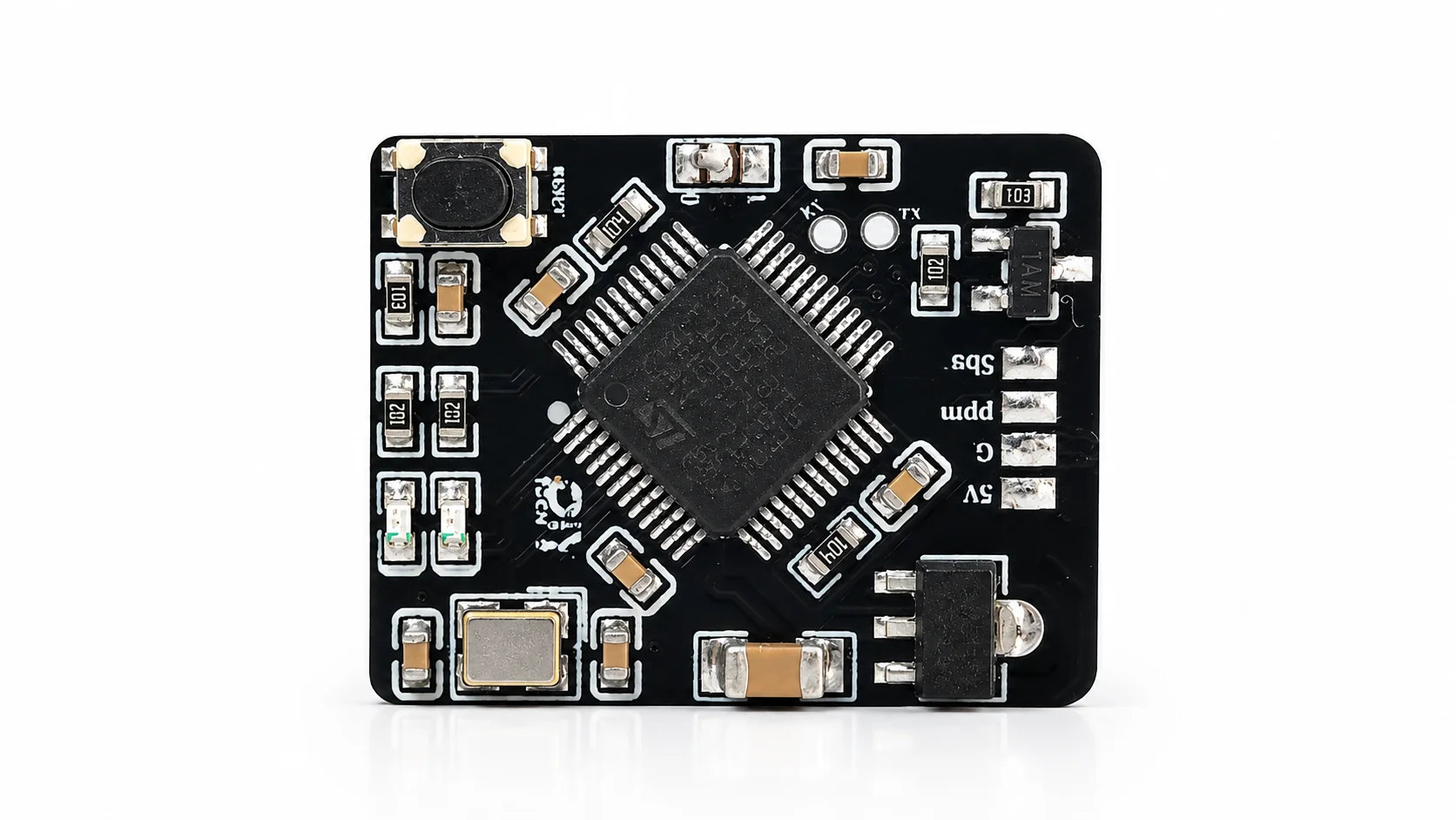
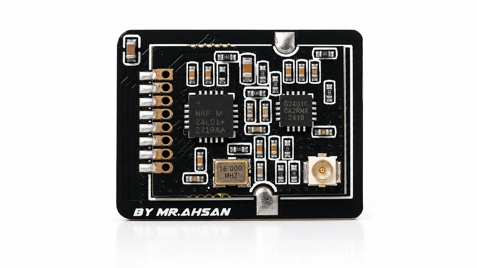
This project is a compact mini SBUS / PPM receiver board designed as a personal embedded RF hardware project. The board is built around an STM32F103C8T6 microcontroller and an nRF24L01+ PA+LNA RF section for 2.4GHz wireless communication.
The receiver is designed to work from a 5V input and provide control signal output through SBUS and PPM interfaces. It includes a power LED for supply indication and a binding LED for receiver bind/status feedback. A tactile button is included for bind or setup interaction, making the board practical for RC receiver-style workflows.
The RF section uses an nRF24L01+ PA+LNA design with an external antenna connector, giving the receiver long-range capability while keeping the board compact and low power. The project was fully tested and confirmed working perfectly, making it a strong personal portfolio example for embedded RF, STM32 firmware, receiver design, and compact PCB layout.
KEY FEATURES
Key Features
TECHNICAL SPECIFICATIONS
| Main MCU | STM32F103C8T6 |
|---|---|
| Board Function | Mini SBUS / PPM 2.4GHz receiver |
| Firmware Role | Receiver logic, bind handling, RF data processing, and signal output generation |
| Input Voltage | 5V input |
| Project Type | Personal embedded RF hardware project |
| RF Chip / Module Section | nRF24L01+ PA+LNA |
|---|---|
| Wireless Band | 2.4GHz RF communication |
| Antenna Interface | External antenna connector |
| RF Focus | Long-range receiver behavior with low-power operation |
| Layout Focus | Compact RF section, clean routing, local passives, and antenna-side placement |
| Output Signal 1 | SBUS |
|---|---|
| Output Signal 2 | PPM |
| Status LED 1 | Power LED |
| Status LED 2 | Binding/status LED |
| User Control | Bind/setup push button |
| PCB Size | 24 × 20 mm |
|---|---|
| Layer Count | 2-layer PCB |
| Copper Weight | 1 oz copper |
| Board Type | Compact RC Receiver |
| Layout Focus | Small footprint, protected power routing,production-friendly assembly |
TEST RESULTS
Test Results
| Test Area | Validation Method | Status | Result / Notes |
|---|---|---|---|
| 5V input validation | Power the receiver board from a 5V input source and verify board startup, MCU operation, and status LED behavior. | Verified | The board was powered from 5V and confirmed working correctly. |
| STM32 firmware validation | Program and run the receiver firmware on STM32F103C8T6, then verify receiver logic, signal handling, and output behavior. | Verified | The STM32F103C8T6 control section was tested and confirmed functional. |
| RF communication validation | Test the nRF24L01+ PA+LNA RF section with the receiver firmware and verify wireless link behavior. | Verified | The RF receiver section was tested and confirmed working with long-range behavior. |
| SBUS output validation | Verify SBUS signal output from the receiver board using the intended RC/control signal workflow. | Verified | The receiver successfully provides SBUS output for compatible control systems. |
| PPM output validation | Verify PPM signal output from the receiver board using the intended RC/control signal workflow. | Verified | The receiver successfully provides PPM output for compatible systems. |
| Power LED check | Apply 5V input and confirm that the power indicator LED shows board power status. | Verified | The power LED provides clear visual confirmation that the receiver is powered. |
| Binding LED check | Test receiver binding/status behavior and verify binding LED indication during the setup workflow. | Verified | The binding/status LED provides visual feedback during receiver setup and connection states. |
| Bind button validation | Press the onboard bind button and verify that the firmware detects the input correctly. | Verified | The onboard button was tested and confirmed working for receiver setup interaction. |
| Complete receiver validation | Test the assembled board as a complete receiver system with RF communication, 5V input, LEDs, bind function, and SBUS/PPM outputs. | Verified | The complete receiver board was tested successfully and confirmed working as intended. |
DELIVERABLES
Deliverables
Project Inquiry
Need a Custom RF Receiver or Control Board?
Send your MCU, RF module, signal output, voltage, and size requirements to get a compact receiver board designed for your application.