PCB design6 min read
High-current PCB layout review checklist
High-current boards fail through systems of small decisions: copper geometry, connector placement, current return paths, switching loops, thermal spreading, and test access. A release review should examine those decisions together.
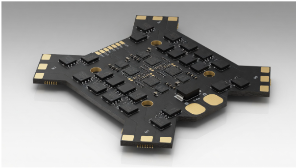
Start with the complete current path
Trace current from the input connector through protection, switching devices, loads, and the return path. Check neck-downs at pads, vias, layer transitions, fuses, shunts, and connectors. A wide pour is not useful when one short section becomes the real electrical and thermal bottleneck. Review continuous and transient current separately, because an ESC or motor-control board can experience short peaks that do not appear in a simple average-current calculation.
Treat heat as a layout constraint
Copper area, device loss, airflow, enclosure conditions, thermal vias, and neighboring temperature-sensitive parts all affect the result. Place heat-producing components where copper can spread energy without heating sensors, references, or connectors unnecessarily. The useful question is not whether a component fits its nominal rating; it is whether the complete board has a believable path for moving heat under the intended operating condition.
Protect control and measurement signals
Gate-drive loops, switch nodes, shunts, current-sense traces, references, and communication lines need deliberate routing. Keep fast switching loops compact, control return paths predictable, and sensitive measurements away from noisy copper. Add accessible test points for rails, enable signals, current sensing, and communication so bring-up does not depend on probing fine-pitch pins during a fault.
- Input connector current rating and cable direction are believable
- No narrow copper neck-downs at pads, vias, fuses, or shunts
- Switching loops are compact and away from sensitive references
- Heat has a real copper, via, airflow, or enclosure path
- Test points exist for rails, enables, communication, and current sensing
Practical takeaway: Before fabrication, review the real current path, worst-case heat path, switching loops, sensitive returns, connector ratings, and test access as one system - not as separate checklist items.
When should a high-current PCB be reviewed?
Review it before fabrication, after placement and routing are stable but before Gerbers are submitted. That is when copper, thermal, connector, and test-access decisions are still cheap to fix.
Is a wide copper pour enough for high current?
No. A wide pour can still fail if the real bottleneck is a pad, via transition, connector footprint, fuse, shunt, or short trace section.
ESP32 IoT7 min read
ESP32 product architecture checklist before manufacturing
A working Wi-Fi prototype is not yet a dependable connected product. Product architecture must account for provisioning, state recovery, firmware updates, power behavior, sensor faults, user feedback, and service access.
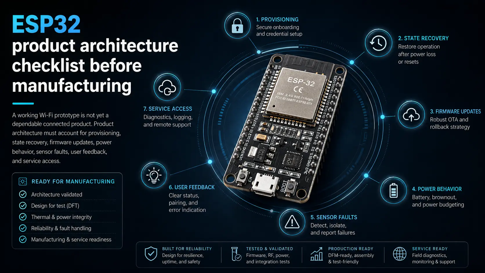
Define device states before writing screens
Map startup, unconfigured, connecting, online, offline, updating, fault, and recovery states. Decide what the physical device does in each state and what the user sees in the dashboard or display. This prevents firmware, electronics, and interface behavior from contradicting one another. It also exposes missing decisions early - for example, whether outputs remain safe when connectivity is lost.
Design provisioning and recovery together
Wi-Fi or BLE setup must work when credentials change, a router disappears, or a user transfers the device. Provide a clear reset path, persistent configuration rules, feedback during connection attempts, and a way to distinguish network failure from device failure. Recovery behavior is part of the product experience, not an edge case to leave until field testing.
Plan hardware for firmware realities
Expose reliable programming and debug access, reserve memory and partition space for updates, review boot-strapping pins, and protect sensors and buses from power sequencing problems. Consider watchdog behavior, brownouts, output defaults, and local operation when cloud or network services are unavailable. A firmware-aware board is easier to bring up and much easier to support after the first prototype.
- Startup, offline, updating, fault, and recovery states are defined
- Provisioning works when credentials change or a router disappears
- Outputs remain safe if cloud or Wi-Fi services are unavailable
- Programming and logs are accessible after assembly
- Dashboard labels match real device states and limits
Practical takeaway: Write the state model, provisioning flow, recovery behavior, update strategy, and safe output defaults before treating the dashboard as finished.
Why is an ESP32 prototype not automatically production-ready?
A prototype usually proves the main idea. A product must also handle provisioning, updates, recovery, safe outputs, power behavior, diagnostics, and support after installation.
Should firmware and dashboard design happen together?
Yes. Planning them together keeps device states, user feedback, warnings, and controls consistent across the hardware and web interface.
Embedded UI6 min read
LVGL UI mistakes on embedded displays and how to avoid them
An embedded touchscreen should be designed around display size, memory, input method, update rate, device states, and operator context. Desktop-style screens often become slow or confusing when transferred directly to a device.
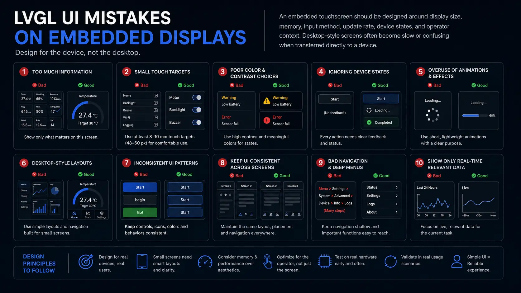
Start with tasks and device states
List the few actions users perform most often and the states they must understand quickly. Status, alarms, setup, manual control, and maintenance should have a clear hierarchy. Avoid forcing users through decorative dashboards when the real task is acknowledging a fault, changing one setting, or confirming that the device is operating safely.
Design within rendering constraints
Screen resolution, color depth, framebuffer strategy, available RAM, image assets, fonts, and animation complexity affect performance. Reuse components and styles, limit unnecessarily large assets, and test transitions on the target hardware early. A smooth, restrained interface usually communicates higher quality than a visually busy screen that misses touch input or updates slowly.
Make implementation states explicit
Each control needs normal, pressed, disabled, active, loading, success, and fault behavior where relevant. Define units, ranges, validation, confirmation, and error feedback. SquareLine Studio can accelerate layout, but the exported LVGL structure still needs disciplined naming, event planning, hardware data binding, and testing with real device states.
- Screens are organized around real user tasks, not decorative dashboards
- Normal, loading, disabled, fault, and confirmation states are designed
- Images and fonts fit the memory and rendering budget
- Touch targets are tested on the real display size
- Terminology matches firmware and product behavior
Practical takeaway: Validate navigation, touch targets, assets, fonts, device-state feedback, and animation performance on the actual display before polishing secondary screens.
Why do LVGL screens feel slow on hardware?
Large assets, heavy animations, too many redraws, limited RAM, and layouts copied from desktop interfaces often make embedded screens feel slow.
Can SquareLine Studio still need engineering review?
Yes. SquareLine helps create screens, but exported structure, naming, states, events, assets, and hardware data binding still need disciplined planning.
Manufacturing7 min read
What files to send for PCB fabrication and assembly
A clean manufacturing package reduces questions, delays, and avoidable assembly mistakes. Before sending a board out, review Gerbers, drill files, pick-and-place data, BOM alternates, board notes, and mechanical constraints together.
Check fabrication outputs as a package
Open the Gerbers in an independent viewer and compare copper, solder mask, paste, silkscreen, board outline, slots, cutouts, and drill layers. Confirm units, layer naming, stackup notes, impedance requirements, copper weight, surface finish, panelization expectations, and any controlled-depth or nonstandard features.
Make assembly data unambiguous
The BOM and pick-and-place files should agree with the schematic, footprint rotations, side of board, manufacturer part numbers, alternates, no-fit parts, and polarity markings. Add notes for connectors, LEDs, diodes, electrolytic capacitors, modules, cables, and parts that are easy to rotate or substitute incorrectly.
Leave bring-up access on the board
Test points, programming headers, current measurement options, boot controls, reset access, and labelled rails reduce bring-up time. A board that is difficult to probe becomes expensive when the first prototype has a fault or a firmware assumption changes.
- Gerbers, drill files, board outline, slots, and stackup notes are included
- Pick-and-place data matches rotations, side, and reference designators
- BOM includes manufacturer part numbers, alternates, no-fit notes, and lifecycle checks
- Polarity, connector, cable, and assembly notes are clear
- Programming, test, and bring-up access are documented
Practical takeaway: Treat fabrication, assembly, sourcing, and bring-up files as one release package. Small inconsistencies are easier to fix before upload than after parts are placed.
Are Gerbers enough for PCB assembly?
No. Assembly usually also needs BOM, pick-and-place data, polarity clarity, no-fit notes, part alternates, and any special assembly instructions.
Should files be checked outside the EDA tool?
Yes. Open Gerbers and drill files in an independent viewer to catch layer naming, outline, mask, drill, and export mistakes before upload.
Drone electronics6 min read
Drone electronics power-distribution review for compact UAV boards
Compact UAV electronics need disciplined power routing, connector placement, thermal planning, EMI control, and service access. A carrier or power board should be reviewed against the real airframe and wiring path, not only the schematic.
Review current flow and connector stress
Power distribution on a drone board is exposed to vibration, current peaks, cable movement, and restricted airflow. Check connector ratings, pad anchoring, copper neck-downs, return paths, and the mechanical direction of cable pull. A connector that is electrically rated can still become the weak point if its placement makes assembly or service difficult.
Keep noisy and sensitive sections separated
Motors, ESCs, regulators, telemetry, GPS, camera interfaces, and control signals should not be treated as equal neighbors. Switching loops, high-current paths, and antenna regions need separation from sensor references, differential pairs, clock lines, and low-level measurements.
Validate the board inside the installation
Mounting holes, standoffs, enclosure walls, airflow, cable exits, and service access can change a good PCB into a frustrating product. Review the board against the target UAV stack before freezing connector orientation and board outline.
Practical takeaway: A UAV board review should include electrical load paths, EMI, mounting, cables, heat, and service access together because the aircraft installation changes the engineering constraints.
Sourcing6 min read
BOM sourcing and alternates for small-batch embedded products
A prototype BOM can pass electrically and still fail commercially. Small-batch products need approved alternates, lifecycle checks, package consistency, supplier choices, and clear assembly notes before a build is scheduled.
Separate critical and flexible parts
Regulators, sensors, RF parts, connectors, crystals, current-sense devices, and protection components often need tighter control than passives. Mark parts that must not be substituted without engineering review and identify where equivalent alternates are acceptable.
Check lifecycle and availability early
Stock can disappear between prototype and assembly. Review lifecycle status, minimum order quantities, lead times, supplier reliability, and package availability before layout is locked. A footprint chosen for one unavailable part can force a board revision later.
Write assembly notes for real decisions
BOM notes should cover alternates, no-fit options, polarity, programming state, cable or harness relationships, and parts that depend on product variants. Clear notes reduce back-and-forth with the assembler and make future revisions easier to understand.
Practical takeaway: A strong BOM is not just a part list. It is a sourcing and assembly plan that protects the product from stock changes, substitutions, and unclear build decisions.